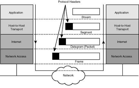
The sending and receiving of data from a source device to the destination device is possible with the help of networking protocols when data encapsulation is used. The data is encapsulated with protocol information at each OSI reference model layer when a host transmits data to another device across a network. Each layer communicates with its neighbor layer on the destination. Each layer uses Protocol Data Units (PDUs) to communicate and exchange information.
Protocol Data Unit (PDU)
Protocol Data Units contain the control information attached to the data at each layer. The information is attached to the data field’s header but can also be at the end of the data field or trailer. PDUs are encapsulated by attaching them to the data at each OSI reference model layer. Each Protocol Data Unit has a name depending on the information each header has. Only the neighbor layer on the destination reads this PU information, which is then stripped off and the data handed to the next layer.

OSI Layer Model and PDUs
The seven layered Open System Interconnection (OSI) layered model is basically defined for reducing the complexity of the internetworking. The OSI model is then divided into two segments for more ease, Upper layers, and Data Flow layers. The 7th, 6th, and 5th layer of the OSI reference model are application layers also known as upper layers. The upper layers are directly related to the user interface while the OSI model’s 4rth, 3rd, 2nd, and 1st layer are also called data flow layers because they are related to the data flow. Each data flow layer has a Protocol Data Unit.
Each data flow layer’s Protocol Data Unit is defined as follows:
- Transport Layer: Segment is the PDU of the Transport layer.
- Network Layer: Packet is the PDU of the Transport layer.
- Data Link Layer: Frame is the PDU of the Transport layer.
- Physical Layer: Bit is the PDU of the Transport layer.
Encapsulation and De-Encapsulation Process
The encapsulation and de-encapsulation of header control information on each OSI reference model layer is as follows:
Encapsulation
The data encapsulation process is defined as below:
TCP Header Encapsulation
The application layers user data is converted for transmission on the network. The data stream is then handed down to the Transport layer, which sets up a virtual circuit to the destination. The data stream is then broken up and a Transport layer header called a segment is created. The header control information is attached to the data field’s Transport layer header. Each segment is sequenced so the data stream can be put back together on the destination exactly as transmitted.
IP Header Encapsulation
Each segment is then handed to the Network layer for logical addressing and routing through a routed protocol, for example IP, IPX, Apple Talk, DECNET, etc. The Network layer protocol adds a header to the segment handed down to the Data Link layer. Remember that the 3rd and 4th layers work together to rebuild a data stream on a destination host. However, they have no responsibility for placing their Protocol Data Units on a local network segment, which is the only way to get the information to host or router.
MAC Header Encapsulation
The Data Link layer receives the packets from the Network layer and places them on the network medium such as cable or wireless medium. The Data Link layer encapsulates each packet in a frame and the MAC header carries the source Mac address and destination Mac address. If the device is on a different network, then the frame is sent to a router to be routed through an internetwork.
Physical Layer Encapsulation
Once the frame gets to the destination network, a new frame is used to get the packet to the destination host. To put this frame on the network, it must first be put into a digital signal. Since a frame is really a logical group of 1s and 0s, the OSI model’s Physical layer is responsible for encapsulating these digits into a digital signal, which devices on the same local network read.
De-Encapsulation
On the destination side, the receiving devices synchronize on the digital signal and extract the 1s and 0s from the digital signal. At this point, the devices build the frames, run a Cyclic Redundancy Check (CRC), and check their output against the output in the data frame’s Frame Check Sequence (FCS) field. If the information matches, the packet is pulled from the frame and the frame is discarded. This process is known as de-encapsulation. The packet then transfers to the Network layer, where the IP address is checked. If the IP address matches, the segment is pulled from the packet and the packet is discarded. The data is processed at the Transport layer that rebuilds the data stream and acknowledges to the transmitting station that it received each segment. It then transfers the data stream to the upper layer application.
At a transmitting device, the data encapsulation method works as follows:
- User information is converted into data for transmission on the network.
- Data is converted into segments and a reliable or unreliable connection is set up between the source and destination devices with connection oriented and connectionless protocols.
- Segments are converted into packets with a logical address such as IP datagram using an IP address.
- Packets are converted into frames for transmission on the local network. Media Access Control (MAC) addresses or Ethernet addresses are commonly used to uniquely identify hosts on a local network segment.
- Frames are converted into bytes and bits and a digital encoding and clocking or signaling method is used.
Videos Related to Data Encapsulation


Michael Hocke
You might want to revise the sentence in the PDU explanation so it reads correctly. I believe the word should be attaching them vice attached them.
“PDUs are encapsulating by attached them to the data”
memenode
Thanks, fixed.