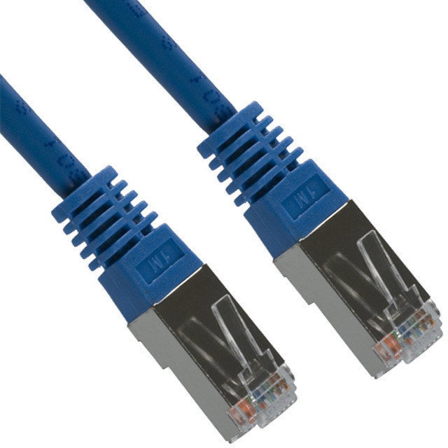
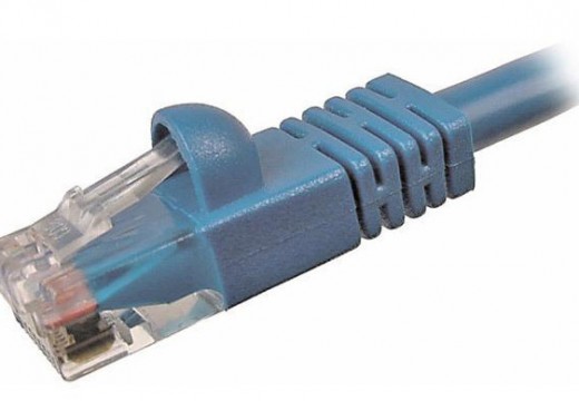
568B, or more formally EIA/TIA 568B, is one of the International standards which include the definition for how the pins or wires in a RJ-45 cable are arranged or terminated. The termination of the cable can occur at several locations which include an individual cable connecting a computer to an Ethernet port, the ending socket of the cable, the termination frame, or an Ethernet patching panel. Within the standards document ISO/IEC11801:1995, the definition for both 568B and the alternate implementation known as 568A are defined. Each configuration is deployed in building and networking infrastructure today.
568B Configuration History
Prior to the publication of the TIA/EIA 568 standard in 1985, AT&T had undergone significant development efforts in creating faster computer networks. The research focused providing networking infrastructure capable of running on the existing telephone infrastructure. Since the existing phone lines were going to be used for the network development, AT&T had to rely on the Universal Service Ordering Code (USOC) as the termination method of the network. In order to make the network work on a single line telephone, the company invented their own method for terminating cables on UTP (Unshielded Twisted Pair) networks. This method was called 258A and it became widely used in UTP networks and throughout the United States.
Developing the TIA/EIA Standard
By 1985, a number of telecommunications companies started to be concerned (publicly) about the lack of a Ethernet cabling standard that was not controlled by a commercial interest (AT&T). As a result, the Computer Communications Industry Association (CCIA) made a request to the Electronics Industry Association (EIQ) to develop such a standard. These efforts took almost six years until the first draft was released in the summer of 1991.
The new standard was labeled EIA/TIA-568 and included much of the work included in the existing AT&T defacto standard of the time. The standard also included a means to support telephones that use two pairs vice one pair of cable which allowed operations on both pairs one and two. Later that year, TSB-36 (Technical Systems Bulletin 36) was issued that included guidance for both category 4 and category 5 cable connections. The next year, TSB-40 was issued which included guidance for using the higher speed UTP for connecting hardware. This bulletin was later updated (January 1994) to cover both fly leads and Rj45 modular jacks.
During this same timeframe, the TIA/EIA-568 standard was updated to officially declare the connector specification to be TIA/EIA 568A and included the existing 258A AT&T standard under a new name/designation of TIA/EIA 568B. Since both standards were widely deployed at the time, they were both included into the International Standard, Generic Cabling for Customer Premises Cabling, ISO/IEC 11801:1995.
What are the Cable Categories in the TIA/EIA Standard?
The TIA/EIA standard does not simply focus on the connectorization definition for network cabling. It includes a variety of other related information to include the categories of un-shielding twisted pair systems. These definitions also include information for the cabling types to include attenuation, allowed amount of cross-talk, and signal bandwidth. At a high level, as the category number of the cable increases, the capacity to support higher data transmission rates of the cable also increases. For example, CAT-3 cable is capable of support data transmission rates of 16 million bits per second and is assessed as being appropriate for a telephone call. Category 5 (CAT-5) cable places additional restrictions on cable cross talk and attenuation. As a result, the cable has a much higher bandwidth capability than CAT-3 or CAT-4 cable. Since CAT-1 and CAT-2 cabling types were only used for voice calls, they were not included in the TIA/EIA standard from the start.
What is the Purpose of CAT-5 Cable?
CAT-5 cable (Category 5) is designed to carry computer network information for networks such as Ethernet. The cable consists of twisted pair cable and provides performance guarantees of speeds up to 100 MHZ and can also be used to transport video or for telephony use. The cable standard is assessed as being sufficient for network speeds up to 1000BASE-T (Gigabit Ethernet) and is commonly connected using modular connectors or punch down blocks. Most CAT-5 cable is not shielded since it relies on differential signaling and the twisted pair design to help eliminate noise from the communications line. The 568B and 568A connector definitions can each be used with CAT-5 cable for termination of the cabling connection depending on the requirements of the termination point(s).
What is USOC?
The USOC (Universal Servicing Ordering Code) was created by Bell Systems and later introduced by AT&T in the 1970s. The system was designed to aid in connecting the homes and businesses of customers to the public telephone network. The system codes were later adopted (partially) by the United States FCC and continue to be used today as part of the Registered Jack (RJ) wiring configurations for telephone jacks. The following letters are found after a RJ number that indicates what mounting or wiring method is employed:
C – Indicates that a flush-mounted or surface jack is in use.
M – indicates that this is a multiple line jack.
S – Indicates that this is a single line jack.
W – Indicates that this is a jack mounted in the wall.
X – Indicates that this is a series or complex multiple line jack.
Additional terms that are commonly associated with the Universal Servicing Ordering Code are:
A/A1 – Indicates that the connection interfaces with the hold function of a key telephone system. The A lead gets shorted to the A1 lead when the line is “off hook” in order to allow the hold functionality to work properly.
Bridged – This indicates that there is a parallel connection.
Data – A specified configuration that uses a jack which includes components designed to limit the overall signal power levels of data producing or transmitted equipment.
T/R – Indicates that the connection leads to the ring and tip wires of a communications channel, facility, line, or trunk.
What is a UTP Network?
A UTP (Unshielded Twisted pair) network uses a copper wire and helps connect homes, businesses, and schools to the telephone network. It is the most commonly used type of twisted pair wiring in industry throughout the world due to its low cost and the relative ease of use when compared to Shielded Twisted Pair (STP). UTP is also incorporated into home and office telephone wiring and Ethernet 10Base-T and 100Base-T networks. In the UTP wiring, there are two copper wires (insulated) that are twisted around one another in order to help decrease the amount of electromagnetic induction between the pairs of wires and to decrease crosstalk that can occur. Every signal transmitted on a UTP wire uses both of the pairs of cable in the wire. If a twisted pair set is enclosed in a shield, it is referred to as STP.
568B Color Codes
| Pin (Jack) | Pin (Plug) | Color | Pair |
|---|---|---|---|
| 1 | 8 | White/Orange | 2 – Tip |
| 2 | 7 | Orange | 2 – Ring |
| 3 | 6 | White/Green | 3 – Tip |
| 4 | 5 | Blue | 1 – Ring |
| 5 | 4 | White/Blue | 1 – Tip |
| 6 | 3 | Green | 3 – Ring |
| 7 | 2 | White Brown | 4 – Tip |
| 8 | 1 | Brown | 4 – Ring |
Pin numbers are read left-to-right with the connector tab facing down.
568B vs 568A
A question that always arises when comparing the 568B vs 568A standards, is which is best to use? There is not a clear cut answer to the question. First, if one is installing additional wiring into an existing building, structure, or home, a best practice is to first determine what type of wiring standard is already in use. Once ascertained, use the same standard for additional wiring throughout the structure to avoid confusion and having to support multiple standards. If installing telephone wiring into a new home or facility, several countries actually recommend (Australia and the United States) to install the EIA/TIA 568 specification.
Looking back at history; however, the 568B specification was the one of choice due to the implementation base and early development. Over time, this has shifted to the 568A standard primarily to ensure as much backward compatibility as possible. This has not reached the point; however, of removing existing 568B installations.
When 568B is compared to the USOC, the blue par on each standard is terminated on the four and five pins. This allows a single USOC phone line to operate on the 568B line. When a USOC phone requires two pairs; however, the green pair replaces the orange on the 568B line and is not completely compatible with the USOC hardware.
The following illustrates how the contacts differ between 568A and 568B when looking down on the cable with the locking tab facing down. The contact numbering scheme goes from left to right, numbers one through eight.
EIA/TIA-568A:
Pin 1: White/Green
Pin 2: Green/White (or just plain Green)
Pin 3: White/Orange
Pin 4: Blue/White (or just plain Blue)
Pin 5: White/Blue
Pin 6: Orange/White (or just plain Orange)
Pin 7: White/Brown
Pin 8: Brown/White (or just plain Brown)
EIA/TIA-568B:
Pin 1: White/Orange
Pin 2: Orange/White (or just plain Orange)
Pin 3: White/Green
Pin 4: Blue/White (or just plain Blue)
Pin 5: White/Blue
Pin 6: Green/White (or just plain Green)
Pin 7: White/Brown
Pin 8: Brown/White (or just plain Brown)
When installing telephone wiring into a new facility, EIA/TIA 568A is the standard to utilize.


blonk chongerhon
You left off whether or not A or B is recommended from the following statement:
If installing telephone wiring into a new home or facility, several countries actually recommend (Australia and the United States) to install the EIA/TIA 568 specification.