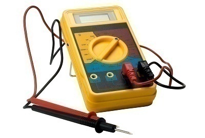
Anyone planning to work on electronics or automobiles that have been manufactured in the past decade, need to be able to use a digital multimeter. Modern multimeters contain three measuring devices in one: an ammeter, voltmeter, and ohmmeter. The top section of the device contains the digital read out and it can be viewed in sunlight.
What Are the Parts of a Digital Multimeter?
The parts of a digital multimeter are fairly common across brands. Beneath the digital readout is the function switch with which the modes that the meter operates, measures, and displays can be changed. There are typically eight positions on a function switch. These include three voltage readouts for AC, DC, and low currents, two amperage slots (one for AC and one for DC current), and Omega for measuring circuit resistance.
How To Measure Voltage with a Digital Multimeter
Step 1 – Turn on the device and allow it to cycle through its startup checks.
Step 2 – Turn the function selector switch to the “V=” position in order to measure DC volts.
Step 3 – Connect the red and black leads to the red input terminal marked “VO” and the black terminal marked “COM” respectively.
Step 4 – Measure voltage by placing the red lead on the terminal that has the higher potential and the black lead on the terminal with lower potential or closer to the ground.
How To Measure Amps with a Digital Multimeter
Step 1 – Set the function selector switch to the “A=” position.
Step 2 – Connect the black lead to the “COM” terminal and the red lead to the “300mA” terminal.
Step 3 – Connect the meter in series to the device whose amperage is being measured by inserting between two points on an open circuit. The output will be displayed in milliamps.
How To Measure Resistance with a Digital Multimeter
Step 1 – Disconnect all power sources and external inputs from the device whose resistance is being measured.
Step 2 – Turn the function selector switch to the “O” position.
Step 3 – Connect the red lead to the “VO” terminal and the black lead to the “COM” terminal. “OL” should be displayed on the multimeter.
Step 4 – Connect the leads across the device whose resistance is being measured.
How to Test a Battery With a Digital Multimeter
Step 1 – Turn on the digital multimeter and allow it to complete its self diagnostic check.
Step 2 – Move the function selector switch to measure DC voltage.
Step 3 – Connect the black probe to the “COM” port and the redo probe to the “V” port.
Step 4 – Place the black lead on the negative terminal or side of the battery, then place the red probe on the positive terminal. The multimeter will now display the battery’s DC voltage output.
Step 5 – Compare the voltage output for the battery type against the following table of ratings for alkaline batteries:
AAA – 1.5V
AA – 1.5V
C – 1.5 V
D – 1.5 V
9V – 9V
New batteries display a slightly lower voltage output and rechargeable batteries are often rated from 1.25V to 1.4 V. When batteries test significantly lower than the above values, it is a good indicator that the user needs to replace or recharge them.


mark'
hom=