RJ-45 is one of the more popular standard connector types used with unshielded, twisted pair network cables. The RJ-45 connector type is commonly used with Ethernet cables and includes eight pins that interface with the cable wires electrically and is sometimes used with shielding cabling. The pin-outs of the connector are defined to provide cable manufacturers the location that wires need to be placed when attaching the cable to a RJ-45 connector type. There are a number of other connector types on the market such as RJ-11 used for telephone cable connections, but are more narrowly shaped.
What is a Registered Jack?
The RJ designation for the RJ-45 cable stands for “registered jack” and indicates that the connection is defined in the international standard for physical network interfaces. The standard defines both the wiring pattern and connecting jack construction for those intended for use in data services or telecommunications equipment. The interfaces defined in the RJ standard include RJ-11, RJ-14, RJ-21, RJ-45, and the RJ-48 connector types. Of the defined connectors, the RJ standard primarily makes use of the 50 pin miniature ribbon and modular connector types depending on the specific RJ type that is defined.
Getting RJ Connector Names Confused
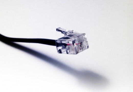
Since the RJ standard defines both the physical geometry and the required wiring pattern, an inspection of just the connector type will not necessarily indicate the type of wiring pattern used in the cable. This is due to the fact that 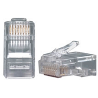 the same connector can be used for different wiring patterns! As a result, there has been a fair amount of confusion by consumers on what type of cable standard is being used depending on the application. For example, the common telephone connector used for RJ-11 is also used for RJ-14 or RJ-25 cables that use four and six wire configurations in the cable as compared to the two used for RJ-11.
Although a connector that is not connected to a cable is not technically an “RJ” type, this commonly happens in industry. The correct method to use for referring to a modular connector is to provide the total number of contact positions and number of wires that the connector can connect or use. As an example, if the designation 4P is used, it indicates a four position modular jack or plug. Then, based on the number of conductors on the plug, the connector description can further be refined. So, if the connector has four positions with the middle two that are conductors, the designation would be 4P2C. The standard RJ-45 connector’s designation is 6P2C, while RJ-14 is 6P4C, and so forth.
What is Twisted Pair?
Backing up a bit, it’s worth taking a moment to explain what is meant by the term, “twisted pair” and how it applies to the RJ-45 and other RJ family of connector/wire types. Typically, when cables are terminated in a RJ connector in building wiring or in any telephone network, they will normally be made up of wires that are twisted in pairs. These wiring conventions were originally designed to help take advantage of creating a standard for physical compatibility of wiring across industry. In the original concept, the center pins on the connector would constitute a single pair of wires, and successively as you moved outward on the connector by groups of two would be counted as an additional pair. On an eight pin connector, there would be a total of four “twisted pairs” of wire.
In order to optimize signal shielding, the ground and hot pins of each pair were to be alternated. Although this meets the requirements for a USOC pin-out, the fourth pair is too far apart to meet the modern-day requirements for the various high-speed LAN protocols. In order to overcome this limitation, the T568A and T568B specifications were created. These standards overcome the limitation by having the outer pins use the adjacent pairs of wire for both the third and fourth pairs of wire. In the T568B standard, the pairs are assigned to different pins than the RJ-14 standard and are incompatible, where in the T-568A version the inner-most four pins are wired identical to RJ-14 and can be interchanged. Due to similar performance of each of these standards over short distances, theT568A and T568B standards are considered equivalent for general or consumer use if having to make a decision on which standard to use. Typically, if there is already one of the two types in use in a building or home, a technician will use the same cable type when installing new equipment or wiring.
History of the RJ-45 Connector
The RJ (registered jack) standard was originally conceived and adopted by the telecommunications industry with the United States FCC (Federal Communications Commission) designated to be the regulating agency. The standard was created in order to define a consistent interface to be used between a customer and the respective phone company. The telecommunications provider is required to provide services to a utility box (or a minimum point of entry, MPOE). This location then connects the network or telephone wiring on the targeted property to the telecommunication network. The customer is then considered responsible for the equipment, wiring, and connection jack(s) located on their side of the terminal box. The establishment of the standard was intended to separate the responsibilities of the wiring and connection(s) between the consumer and the respective telephone company.
This work followed the practice seen under the Bell System monopoly that came after the Communications Act of 1934. In this timeframe, the Bell Systems company owned phones that were used in the home and did not permit the interconnection of additional terminal equipment or separate phones. These phones were normally either hardwired or made use of a proprietary Bell System connector. This practice took more than a decade to change from the mid-1950s to the mid-1960s across the Hush-A-Phone vs. the United States 1956 case and the Carterfone decision by the FCC in 1968. These cases required Ma. Bell to start allowing the interconnection of telecommunication cables that ultimately resulted in the RJ standard being produced.
RJ (registered jacks) started to be introduced under a 1976 FCC order that made the use of protective couplers by the telephone company illegal. The newer phone jacks replaced the more bulky, proprietary jacks and were defined by specifications issued by the Bell System under the USOC (Universal Service Order Codes) which served as the only 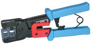 telecommunication connection standards at the time. Due to the numerous options available for the standardized interface options at the time, the onus was placed on the customer to identify the type of interface required under the USOC definitions. For multi-line interfaces such as found with the RJ-21 interface, the customer was required to define what position(s) on the interface would be used to the phone company.
As the telephone industry started to open up to increased competition in the 1980s, the deFacto specifications seen prior to this time became codified under U.S. law under the Code of Federal Regulations, Title 47 CFR Part 68. In 1999, this law was revised under TR5-1999. Just two years later, the U.S. FCC would further delegate the responsibility for enforcement of standardized connections for phone networks to the ACTA (Administrative Council for Terminal Attachments). As part of the delegation to a private entity, the U.S. FCC removed Subpart F from the law and added Subpart G which included the delegation of responsibility to the ACTA. Under the organization’s new responsibilities, the ACTA creates recommendations for new or updated terminal attachments from new or updated standards that are produced by the TIA (Telecommunications Industry Association).
At the time of this writing, the most current version of the standard is TIA-968-A. This specification includes the modular connection definition and incorporates the wiring specifications included in TR5-1999 for the wiring component. Starting with the publication of TIA-968-B, the connector descriptions were moved to the TIA-1096-A definition. RJ descriptors continue to identify both the physical connector and associated wiring pinouts.
How are RJ-45 Connectors categorized?
Registered Jack-45, or RJ-45 is most commonly used in industry today for the wiring and connections uses for high-speed networks. The technical name for the physical connector used for the RJ-45 standard is the 8P8C modular connector (the more formal categorization is the International Electrotechnical Commission (IEC) 60603-7 8P8C modular connector). The original meaning of the 8P8C descriptor was to describe the eight positions and eight contacts in the connector. Since that time; however, it has been revised to stand for eight positions and eight conductors. Every 8P8C plug used in the RJ-45 standard is required to be 21.46 mm long by 11.68mm high and 8.30 mm wide. RJ-45 plugs are able to support either stranded or solid wire and are not known to have good performance when used with incorrect wiring. The same specialized crimping tools are used to terminate RJ-11 plugs as are required for the RJ-45 type.
What are the RJ-45 Applications?
RJ-45 or 8P8C connectors are most commonly found in telephone and networking applications with the plug on one end of the wire ending in an 8P8C connection in accordance with one of the two current TIA/EIA standards. The majority of Ethernet connected networks today use this type of connection carried over either Category 6 or Category 5e cable. The 8P8C connector is also commonly used for RS-232 serial cable interfaces as defined by the EIA/TIA-561 standard. For this application of the standard, the cable and plug is used for console interface tasks on network routers and switches. They are also commonly used to support high-speed ISDN and T-1 networking lines.
The RJ-45 connector is also commonly used in floodwired environments where the blue pair is commonly used for transport of telephone or networking signals. In these cases, the RJ-45 plug (8P8C) permits a RJ-11 plug to be used in the center of the jack as long as the RJ-11 plug is wired in strict compliance with the U.S. standard making use of the center pair of wires.
In these cases, the remaining pair on the plug can be used for PoE (Power over Ethernet) applications. In other applications, a number of bridges, routers, and switches are designed to use the unused four wires in the RJ-11 configuration to carry current to the plugged-in component. For newer PoE supported components, there is a newer wiring scheme that better optimizes the available capacity of the wiring.
8P8C connectors that are used in RJ-45 connections also commonly find use as microphone connectors for amateur radio transceivers. In this application, the pinout will differ from network connections, but usually mirror what is found in the TIA/EIA-568 standard.
For landline applications, the 8P8C jack is use for the point that a phone line enters a building or structure to allow it to connect to telephones, networks, or alarm panels. In legacy applications, the 8P8C connection was used to connect the AMPS cellular handsets to base units (no longer practiced on new installations).
Prior to the spread of high-speed Internet connections in the home, the RJ-45S connector was used for modem and data connections. The RJ-45S connector made use of a keyed 8P8C connector body with an additiona tab that prevented it from connecting or touching additional connectors. Although the difference in look with modern 8P8C connectors is slight, the difference is significant enough to represent a different connector.
Today, almost all 8P8C modular connectors are marketed as the “RJ-45” type. The connector can be wired to just about any pin-out using RJ-45 patch panels for both data and legacy phone use.

Follow Us!